
TEL 203/03 Process Control and Instrumentation Course Assessment 2 (CA2 – 30%)
Assignment Type
Individual Assignment
Subject
TEL 203/03 Process Control and Instrumentation
Uploaded by Malaysia Assignment Help
Date
10/24/2025
Evidence of plagiarism or collusion will be taken seriously, and the University regulations will be applied fully. You are advised to be familiar with the University’s definitions of plagiarism and collusion.
Instructions:
- This is an individual assignment. No duplication of work will be tolerated. Any plagiarism or collusion may result in disciplinary action, in addition to the ZERO mark being awarded to all involved.
- You are to submit online of your answers in OAS system and it is your responsibility to submit your CA correctly and timely. OAS system does not allow re-submission of the assignment. Marks will be awarded for correct working steps and answers.
- The total marks for CA2 are 100 and contribute 30% towards the total grade.
- CA2 must be done individually.
- Your assignment must be word-processed (single spacing) and clearly laid out. Any additional appendices or attachments must be placed at the end of the submitted document and must be referred to in the main body of the assignment, or it will not be read by the marker.
- All files or documents submitted must be labeled with your WOU ID and name.
- Please be advised to use following naming convention to your assignment:
<class code>_<student ID>_CA2
PLAGIARISM DECLARATION FORM (T-DF)
InstructionsPlease complete and attach this Plagiarism Declaration Form to each Assignment that you submit into the Online Assignment Submission (OAS) system for marking. |
| I declare that the attached work is entirely my own (or when submitted to meet the requirements of an approved group assignment is the work of the group), except where materials cited, quoted or paraphrased are acknowledged in the text. I also declare that this work / assignment has not been submitted for assessment in any other course or university without due acknowledgement.
I understand that plagiarism, collusion, and copying are grave and serious offences. I understand that disciplinary action (which may include deduction of marks in the Assignment) will be taken against me if I am found to be an offender of Assignment plagiarism. Full name and IC No: Date |
| Assignment (Asgmt) Declaration Form | |
| Semester/Year | |
| Student’s Name | |
| Student’s ID No: | |
| Course Code | |
| Course Title | |
| Class Code | |
| Assignment No: | |
| No. of pages of this Assignment (including this page) | |
| Tutor | |
| Course Coordinator | DR Mohd Hezri Bin Marzaki |
T-DF Assignment Declaration Form (1/2020 version #003)
Rubric Lab 1
| QUESTION
|
Mark(s) | Grade | ||||
| F, D- , D | C-, C , C+ | B-, B, B+ | A-, A | |||
| Poor | Mediocre | Good | Outstanding | |||
| Weight | 0.25 | 0.5 | 0.75 | 1 | ||
| Lab 1 | 1.Write the short introduction, some explanation on TRiLOGI software and experimental procedure | 10 | The question answered is erroneous or irrelevant
|
The question answered is partially identified and is stated in a somewhat unclear manner. | The question answered is identified but is stated in a somewhat unclear manner. | The question answered is identified but is clearly identified and stated. |
| 2. By using the TRiLOGI software, simulate the steps and generate the ladder diagram. You should capture results based on each condition of your simulations and present them in your report. You may use “Print Screen” to capture your simulation results. You must also include the ladder diagram generated from your simulations in your report. | 30 | Needed diagrams are missing OR are missing important labels. | Diagrams are included and are labelled. | Diagrams are included and are labelled neatly and accurately. | Clear, accurate diagrams are included and make the experiment easier to understand. Diagrams are labelled neatly and accurately. | |
| 3. Write a short report to discuss your answers. discussion on explanation on ladder logic and the results you obtain at every stages of the simulation. | 10 | Report illustrates inaccurate understanding of ladder logic, concepts underlying the lab. | Report illustrates a limited understanding of ladder logic, concepts underlying the lab. | Report illustrates an accurate understanding of most ladder logic, concepts underlying the lab. | Report illustrates an accurate and thorough understanding of ladder logic, concepts underlying the lab. | |
Stuck in This Assignment? Deadlines Are Near?
Lab Exercise 1 (50 Marks)
Title:
Ladder Logic Programming Using TRiLOGI
Objective:
To explain the concept and procedure in designing the ladder diagram (CLO1/3, P2)
Software:
TRiLOGI
Procedures
Below is a brief procedure to guide you to download and install the TriLogi freeware which will be used during the de-couple lab session for TEL203/05. This freeware is only valid within seven days after installation. Hence it can only be installed a few days prior to the de-couple lab session. Please kindly follow the procedures as listed below:-
- Click on the link below to go to the webpage where the freeware can be downloaded.
http://www.triplc.com/iTrilogi6Edu/
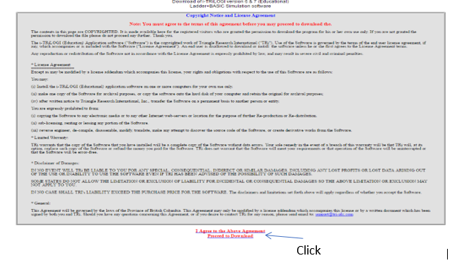
- Then, you will see the figure below.

- Click on the statement in red which read “I Agree to the Above Agreement Proceed to Download”.
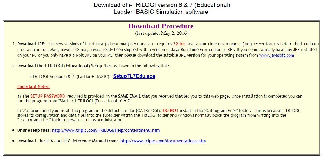
- You will then be directed to the below page:

- Click on “SetupTL7Edu.exe” to begin download.

- Follow the procedure as you are being prompted to install the freeware. You will be prompted to key in the password (please see below):-
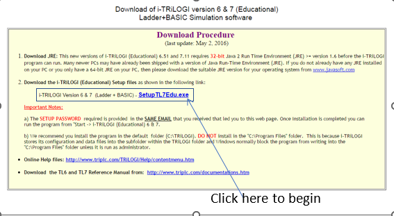
Password: LadderBasic2009
Results
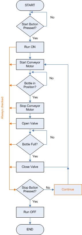
By using the TRiLOGI software, simulate the steps and generate the ladder diagram based on narrative statement, input and output port table and flowchart below. You should capture results based on each condition of your simulations and present them in your report. You may use “Print Screen” to capture your simulation results. You must also include the ladder diagram generated from your simulations in your report.
1. Narrative Statement
I) Start the bottle conveyor
ii) When a bottle is in position
a. Stop the conveyor
b. Open the output valve
iii) When the bottle is full
a. Close the output valve
iv) Repeat i)
2. Input and Output Port Table
| Input Port | Output Port | ||
| X0 | Start | Y0 | Conveyor Motor |
| X1 | Stop | Y1 | Valve |
| X2 | Sensor BP | ||
| X3 | Sensor BF | ||
3. Flow chart
Discussion
Write a short report to discuss your answers. Your report should contain a short introduction, some explanation on ladder logic, your experimental procedure, and the results you obtain at every stage of the simulation.
Rubric Lab 2 (CLO1/3)
| QUESTION
|
Mark(s) | Grade | ||||
| Poor | Mediocre | Good | Outstanding | |||
| Weight | 0.25 | 0.5 | 0.75 | 1 | ||
| Lab 2 | 1.Write the short introduction, some explanation on Wheatstone bridge simulation and experimental procedure | 5 | The question answered is erroneous or irrelevant
|
The question answered is partially identified and is stated in a somewhat unclear manner. | The question answered is identified but is stated in a somewhat unclear manner. | The question answered is identified but is clearly identified and stated. |
| 2.You are required to include a picture of circuit output results in your report
-Measure and record (screenshot) the value of voltage between point V1 and V3?. -Verified the answer in (1) with the theoretical calculation. -Explain why is voltage between point V1 and V3 has minus sign? -Find value of Rx if R1=1 kΩ, R2=3 kΩ and R3=4 kΩ under balance condition. (measure and record (screenshot) |
15 | The question answered is erroneous or irrelevant.
Needed diagrams are missing OR are missing important labels. |
The question answered is partially identified and is stated in a somewhat unclear manner.
Diagrams are included and are labelled. |
The question answered is identified but is stated in a somewhat unclear manner.
Diagrams are included and are labelled neatly and accurately. |
The question answered is identified but is clearly identified and stated.
Clear, accurate diagrams are included. Diagrams are labelled neatly and accurately. |
|
| 3. Write a discussion for this lab. The discussion should be as detailed as possible covering the following aspects:
-Operation of Wheatstone bridge simulation |
5 | Report illustrates inaccurate understanding of limitation circuit design underlying the lab. | Report illustrates a limited understanding of limitation circuit design underlying the lab. | Report illustrates an accurate understanding of most limitation circuit design concepts underlying the lab. | Report illustrates an accurate and thorough understanding of limitation circuit design concepts underlying the lab. | |
Lab 2 (25 Marks)
Title:
Wheatstone bridge simulation
Objective:
To construct and analyze Wheatstone bridge using Multisim Live (Drag and Drop) (CLO1/2/3, C4, P5)
Software:
Multisim Live
Procedure:
1. Open the following lab:
2. Click on sign up to create free account or login using an existing account.

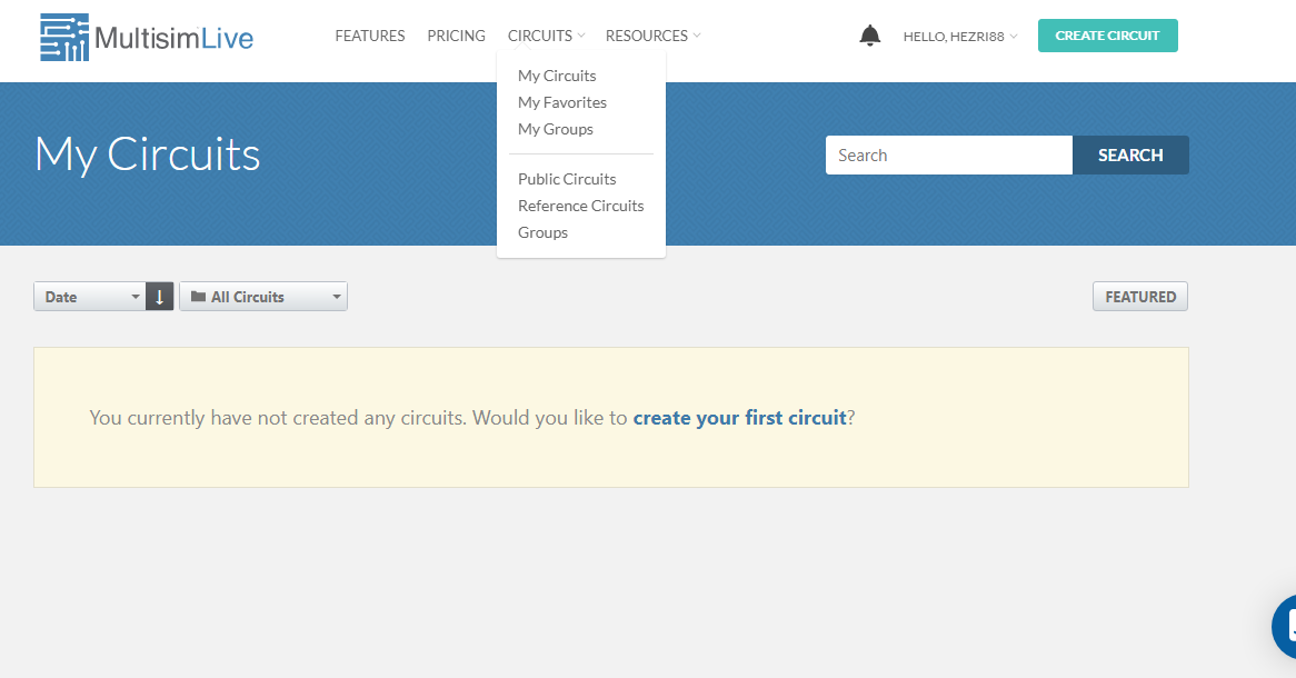
3. After you create/ log in the account. Click on CIRCUITS>MyCircuits
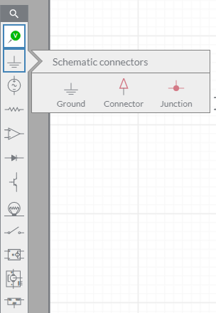
4. A blank workspace will appear. Drag and drop the following items from the leftside panel into the workspace.
i) Ground
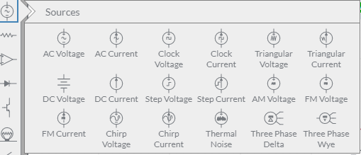
ii) DC Voltage
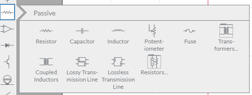
iii) Resistor
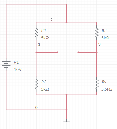
5. Construct the circuit as shown in figure below. Ensure the circuit is properly connected
Tips on how to place voltage indicator: Drag and drop the junction from the leftside panel into the workspace
i) Connect the 1st junction to wire 1
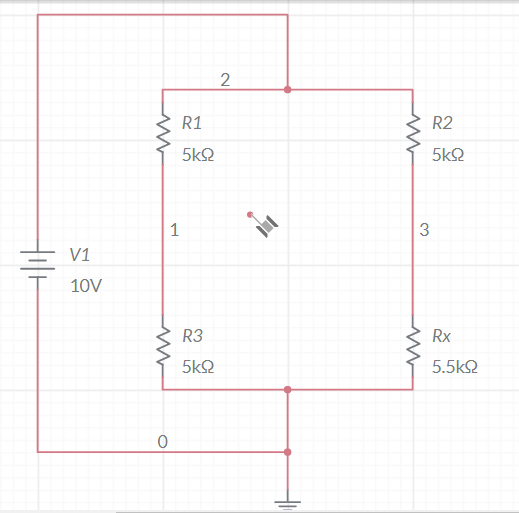
ii) Connect the 2nd junction to wire 3
iii) Place voltage indicator at junction 1
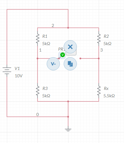
iv) Click at V-, and place at junction 2
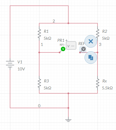
v. Click the play button, and observed the reading.

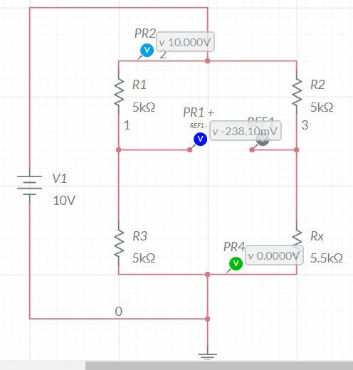
Results
- Measure and record (screenshot) the value of voltage between point V1 and V3?.
- Verified the answer in (1) with the theoretical calculation.
- Explain why is voltage between point V1 and V3 has minus sign?
- Find value of Rx if R1=1 kΩ, R2=3 kΩ and R3=4 kΩ under balance condition. (measure and record (screenshot)
Discussions:
Write a short report to discuss your answers. Your report should contain a short introduction, some explanation on Wheatstone bridge simulation, your experimental procedure, and the results you obtain at every stages of the simulation
Rubric Lab 3 (CLO1/3)
| QUESTION | Mark(s) | Grade | ||||
| Poor | Mediocre | Good | Outstanding | |||
| Weight | 0.25 | 0.5 | 0.75 | 1 | ||
| Lab 3 | 1.Write the short introduction, some explanation on binary weighted resistor & R/2R ladder and experimental procedure
|
5 | The question answered is erroneous or irrelevant
|
The question answered is partially identified and is stated in a somewhat unclear manner. | The question answered is identified but is stated in a somewhat unclear manner. | The question answered is identified but is clearly identified and stated. |
| 2.Complete the tables in result section. You are required to include a picture of circuit output results in your report
|
15 | Unable to complete table. Needed diagrams are missing OR are missing important labels. | Partially complete the table.
Diagrams are included and are labelled. |
Almost complete the table.
Diagrams are included and are labelled neatly and accurately. |
Complete all the table. Clear, accurate diagrams are included. Diagrams are labelled neatly and accurately. | |
| 3. Write a discussion for this lab. The discussion should be as detailed as possible covering the following aspects:
-Operation of binary weighted resistor and R/2R ladder
|
5 | Report illustrates inaccurate understanding of limitation circuit design underlying the lab. | Report illustrates a limited understanding of limitation circuit design underlying the lab. | Report illustrates an accurate understanding of most limitation circuit design concepts underlying the lab. | Report illustrates an accurate and thorough understanding of limitation circuit design concepts underlying the lab. | |
Get 30% Discount on This Assignment Answer Today!
Lab 3 (25 Marks)
Title:
DAC simulation by using binary weighted resistor and R/2R ladder
Objective:
To construct and analyze binary weighted resistor and R/2R ladder using Multisim Live (Drag and Drop) (CLO1/2/3, C4, P5)
Software:
Multisim Live
Procedure:
1. Open the following lab:
2. Click on sign up to create free account or login using an existing account.
3. After you create/ log in the account. Click on CIRCUITS>MyCircuits
4. A blank workspace will appear. Drag and drop the following items from the leftside panel into the workspace.
i) Ground
ii) DC Voltage
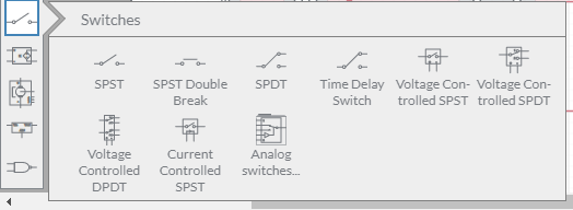
iii) SPST
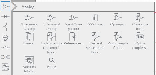
iv) 3 Terminal Opamp
v) Resistor

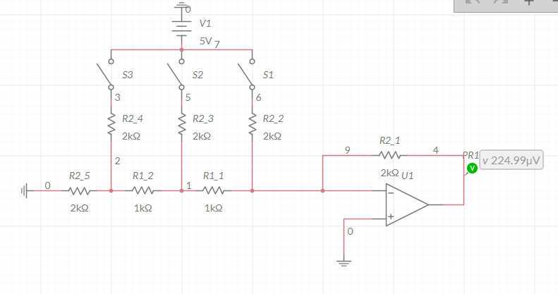
Part 1: 3-bit binary weighted resistor
1. Construct the circuit as shown in figure below. Ensure the circuit is properly connected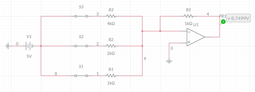
2. Click the play button, and observed the reading.
3. Modify circuit above into 4-bit binary weighted resistor. Observed and record the reading
Part 2: 3-bit R/2R ladder
1. Construct the circuit as shown in figure below. Ensure the circuit is properly connected
2. Click the play button, and observed the reading.
3. Modify circuit above into 4-bit R/2R ladder. Observed and record the reading.
Results and Discussions:
Part 1: Binary weighted resistor and R/2R ladder
Record the value of Vout in for 3bit-binary weighted resistor table below:
| S1 | S2 | S3 | Vout |
| 1 | 1 | 1 | |
| 1 | 1 | 0 | |
| 1 | 0 | 1 | |
| 1 | 0 | 0 | |
| 0 | 1 | 1 | |
| 0 | 1 | 0 | |
| 0 | 0 | 1 | |
| 0 | 0 | 0 |
Record the value of Vout for 4bit-binary weighted resistor table below:
| S1 | S2 | S3 | S4 | Vout |
| 1 | 1 | 1 | 1 | |
| 1 | 1 | 1 | 0 | |
| 1 | 1 | 0 | 1 | |
| 1 | 1 | 0 | 0 | |
| 1 | 0 | 1 | 1 | |
| 1 | 0 | 1 | 0 | |
| 1 | 0 | 0 | 1 | |
| 1 | 0 | 0 | 0 | |
| 0 | 1 | 1 | 1 | |
| 0 | 1 | 1 | 0 | |
| 0 | 1 | 0 | 1 | |
| 0 | 1 | 0 | 0 | |
| 0 | 0 | 1 | 1 | |
| 0 | 0 | 1 | 0 | |
| 0 | 0 | 0 | 1 | |
| 0 | 0 | 0 | 0 |
Part 2:
Record the value of Vout for 3-bit R/2R ladder table below:
| S1 | S2 | S3 | Vout |
| 1 | 1 | 1 | |
| 1 | 1 | 0 | |
| 1 | 0 | 1 | |
| 1 | 0 | 0 | |
| 0 | 1 | 1 | |
| 0 | 1 | 0 | |
| 0 | 0 | 1 | |
| 0 | 0 | 0 |
Record the value of Vout for 4-bit R/2R ladder table below:
| S1 | S2 | S3 | S4 | Vout |
| 1 | 1 | 1 | 1 | |
| 1 | 1 | 1 | 0 | |
| 1 | 1 | 0 | 1 | |
| 1 | 1 | 0 | 0 | |
| 1 | 0 | 1 | 1 | |
| 1 | 0 | 1 | 0 | |
| 1 | 0 | 0 | 1 | |
| 1 | 0 | 0 | 0 | |
| 0 | 1 | 1 | 1 | |
| 0 | 1 | 1 | 0 | |
| 0 | 1 | 0 | 1 | |
| 0 | 1 | 0 | 0 | |
| 0 | 0 | 1 | 1 | |
| 0 | 0 | 1 | 0 | |
| 0 | 0 | 0 | 1 | |
| 0 | 0 | 0 | 0 |
Discussions:
Write a short report to discuss your answers. Your report should contain a short introduction, some explanation on binary weighted resistor and R/2R ladder, your experimental procedure, and the results you obtain at every stage of the simulation.
End of Course Assessment 2
Get Solved Your Assignment(variable) and Earn A+ Grade!
Get Help By Expert
Working on your Process Control and Instrumentation assignment can be tough, especially with TRiLOGI simulations, ladder logic diagrams, and Wheatstone bridge experiments. If you’re struggling to get accurate results or explain your findings clearly, expert help can make it easier. At Malaysia Assignment Helper, we provide course work assignment help that’s 100% plagiarism-free, AI-free, and tailored to university marking rubrics. Get reliable guidance today with our engineering assignment help Malaysia services.

Recommended Assignments for You
Related University Assignments
- LSS312/05 Principles of Social Research Final Assessment 2026 | WOU
- MPU3183 Appreciation of Ethics and Civilisations Assignment Brief 2026
- TEE314 Microelectronics Course Assignment 2 Brief 2026 | WOU
- MPU3193 /MCMPU3193 Philosophy and Current Issues Assignment 2, 2026
- MCBMG311/03 Micro – Credential in Employment Law and Industrial Relations Assessment 3 Question 2026 | WOU
- TEE208/03 Circuit Theory II Assignment 2, 2026 | Wawasan Open University
- TEL 203/03 Process Control and Instrumentation Course Assessment 2 (CA2 – 30%)
- The Challenges Teaching English to Refugee Children Research Proposal Case Study
- TEE106/03 Basic Electromagnetic Theory Assignment 1 (25%)
- WUC118/03 Computing & Digital Transformation Assignment: Case-Based Analysis on Cloud, Cybersecurity & Emerging Technologies

Convincing Features