Evidence of plagiarism or collusion will be taken seriously and the University regulations will be applied fully. You are advised to be familiar with the University’s definitions of plagiarism and collusion.
Instructions
This is an individual assignment. No duplication of work will be tolerated. Any plagiarism or collusion may result in disciplinary action in addition to ZERO mark being awarded to all involved.
Submit your assignment to the Online Assignment Submission (OAS) system. Submission of assignments in hard copy will not be accepted.
The total marks for Assignment 2 are 100 Marks and contributes 25% towards the total grade. Marks will be awarded for correct working steps and answer.
Your assignment must be word processed in Time New Roman 12pt font. Answer all questions in English. Any additional appendices or attachments must be placed at the end of the submitted document. Handwritten assignments and photo snap shot will not be accepted.
Students are required to attach the Assignment Declaration Form as the front cover of their assignments. No duplication of work will be tolerated. Any plagiarism or collusion may result in disciplinary action to all parties involved.
Struggling with TEE208 Circuit Theory II Assignment at WOU Malaysia?
A filter is a circuit that attenuates signal components based on their frequencies. Filters are characterized by what range of frequencies they affect and by their order, which represents the degree of attenuation.
Frequency Ranges of Filters
Low-Pass
Attenuates frequency components above a certain threshold
High-Pass
Attenuates frequency components below a certain threshold
Bandpass
Passes a contiguous range (band) of frequencies and attenuates frequencies outside that band
Band-Reject or Notch
Attenuates a band of frequencies
Constructions of Filters
Passive
Consist of passive components (resistors, capacitors, and inductors)
Active
Contain active components such as transistors and op amps.
Digital
Signals are digitized and processed as sets of digital values by logic circuitry or by firmware running on a processor.
Passive Filters
Passive filters consist of passive components: resistors, capacitors, and inductors. A quick way to determine what range of frequencies an arrangement of passive components will attenuate is to consider that capacitors act as short-circuits to high- frequency components and act as open-circuits to low-frequency components. Inductors are the opposite. And, resistors affect all frequency components equally.
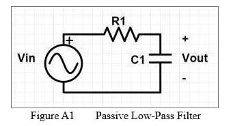
A) Passive Low-Pass Filter
The circuit shown in Figure A1 has just one reactive component, the capacitor C1. R1 and C1 form a voltage divider. By the voltage divider formula:
Vout = Vin * ZC1/(ZR1+ZC1). (Eq. 1)
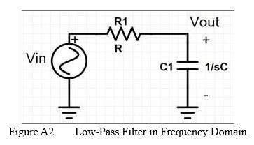
The capacitor C1 has high impedance to low-frequency components. So, at low frequency its impedance will be large resulting in the value of the transfer function being large. This means the filter passes low-frequency components. At high- frequency, the capacitor trends towards being a short circuit, so the value of the transfer function will be minimal at high frequency meaning the filter attenuates high-frequency components. The impedance of the capacitor is 1/sC, and the impedance of the resistor is R as shown in Figure A2.
Figure A2 Low-Pass Filter in Frequency Domain
The transfer function, Vout/Vin, is then:
Vout/Vin = 1/(sC1R1+1). (Eq. 2)
Note a couple things about this transfer function. First, it cannot be greater than one, because resistance and capacitance of the components are positive numbers. When the transfer function has a value range of 1 or less, then it only attenuates and does not amplify. This will always be the case with passive filters, they only attenuate and their transfer functions always have a value less than 1.
Second, note that the numerator is a constant, and the denominator is a single order polynomial of s. This means that it is a 1st-order filter, since the order of a filter is the highest order of polynomial (highest power of s) in either the numerator or denominator of its transfer function. Transfer functions of circuits consisting of passive components will always be ratios of polynomials. This filter has no zeros and one pole at -1/RC,
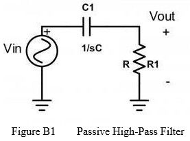
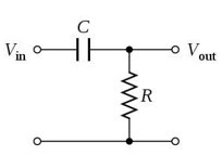
B) Passive High-Pass Filter
A high-pass filter passes high-frequency components and stops low-frequency components. If we swap positions of the resistor and the capacitor so that the capacitor is now in series with the signal we transform to a high-pass filter.
Figure B1 Passive High-Pass Filter
By the voltage divider formula,
Vout = Vin * ZR1/(ZR1+ZC1) (Eq. 3)
Then, the transfer function,
Vout/Vin = R1/(R1+1/sC1) (Eq. 4)
Based on the transfer function this is a first order filter, since there is no power of s higher than 1. Also, it has one zero at S = 0, and one pole at s = -1/RC. The cutoff frequency is determined by the pole, and therefore is the same as for the low-pass filter.
EXPERIMENT 1: Low pass filter
Objective:
To design, build, and analyze an RC low-pass filter, measure the frequency response (amplitude and phase shift), and perform a transient analysis to observe the time-domain behavior of the filter when subjected to a step input signal.
Theory:
A low-pass filter allows signals with frequencies below a certain cutoff frequency to pass through while attenuating higher frequencies. For an RC circuit, the cutoff frequency is defined as:
𝑓𝑐 = 1/2𝜋𝑅𝐶
where:
𝑓𝑐 is the cutoff frequency in Hz,
R is the resistance in ohms (Ω), C is the capacitance in farads (F).
The cutoff frequency of a low-pass filter is defined as the frequency at which the output signal power drops to half of its maximum value, or equivalently, where the voltage amplitude drops to (approximately 0.707) of the maximum value.
In terms of decibels (dB), this corresponds to a −3 dB point. The −3 dB cutoff frequency is a key characteristic of the filter’s behavior.
Cutoff Frequency at −3 dB:
The voltage gain of a simple RC low-pass filter is given by:
|𝐻(𝑓)| = 𝑉𝑜𝑢𝑡 = 1
𝑉𝑖𝑛
where:
f is the input signal frequency,
fc is the cutoff frequency, Vout is the output voltage, • Vin is the input voltage.
At the cutoff frequency fc, the gain drops to , which is equivalent to −3 dB. This can be derived from the gain equation:
|𝐻
Thus, the cutoff frequency fc corresponds to the frequency at which the output signal amplitude drops by −3 dB relative to the maximum passband amplitude.
The phase shift θ(f) for an RC low-pass filter are given by:
−1 (𝑓 )
𝜃(𝑓) = − tan
𝑓𝑐
At the cutoff frequency fc, the phase shift is −45o. At low frequencies, the phase shift is close to 0o, and at high frequencies, the phase shift approaches −90o.
An RC low-pass filter not only affects the frequency response but also introduces a delay when responding to rapid changes in the input signal. This time-domain behavior can be studied using a transient analysis.
In the time domain:
The voltage response of the RC circuit to a step input signal exhibits a characteristic charging behavior for the capacitor.
The time constant τ = RC determines how quickly the circuit responds to changes in the input signal.
The voltage across the capacitor, VC(t), as a function of time in response to a step input is given by:
𝑡
𝑉𝐶(𝑡) = 𝑉𝑖𝑛 (1 − 𝑒−𝑅𝐶)
where:
VC(t) is the voltage across the capacitor at time ttt,
Vin is the magnitude of the step input,
τ = RC is the time constant,
t is the time elapsed since the step was applied.
The capacitor voltage approaches the input voltage asymptotically, and the time constant τ determines how quickly this happens. After approximately 5 time constants (τ), the capacitor voltage is considered to have settled to 99% of the input value.
Components and equipments required:
Resistor (R)
Capacitor (C)
Function generator (for providing input signal)
Oscilloscope (to measure output signal)
Breadboard and connecting wires
Multimeter (for measuring resistance and capacitance)
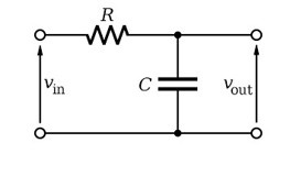
Circuit Diagram:
Where:
R is the resistor,
C is the capacitor,
Vin is the input signal,
Vout is the output signal after passing through the low-pass filter.
Procedure:
Circuit Construction: o Set up the RC low-pass filter circuit on a breadboard. Connect the resistor and capacitor in series.
Connect the input signal (Vin) from the function generator to the point where the resistor and capacitor meet.
Connect the output signal (Vout) from the junction between the resistor and capacitor. o Ensure the ground of the function generator and oscilloscope are connected to a common ground.
Component Selection:
Choose values for the resistor R and capacitor C. For example, select R = 10 kΩ and C =100 nF.
Calculate the cutoff frequency using the formula:
Calculate the time constant τ = RC:
𝜏 = 10 𝑘Ω × 100 𝑛𝐹 = 1 ms
Signal Generation:
Set the function generator to produce a sinusoidal signal with an amplitude of 1 V (or any appropriate level) and start at a low frequency (e.g., 100 Hz).
For transient analysis, set the function generator to produce a step input signal (rather than a sinusoidal signal) or square wave.
Measure and Record Response:
Observe the input and output waveforms on the oscilloscope. o Gradually increase the frequency of the input signal and note the amplitude of the output at various frequencies.
Record the output voltage at different frequencies and identify the frequency at which the output voltage starts to decrease significantly. This is around the cutoff frequency.
At the cutoff frequency, record the phase difference between the input and output signals.
The oscilloscope can be used to measure the phase shift directly between the input and output waveforms. If necessary, use a second channel to measure both the input and output signals simultaneously.
Also, use the oscilloscope to capture the transient response and display both the input and output waveforms for comparison. This is when a step input is applied to the circuit.
Frequency Sweep: o Increase the frequency in small steps (e.g., 100 Hz, 200 Hz, 500 Hz, 1 kHz, etc.), and for each frequency, measure the output amplitude.
o Plot the measured output voltage against the input frequency to create a frequency response curve.
Plot and Analysis:
The output signal should show full amplitude at low frequencies (below the cutoff frequency).
As the frequency approaches the cutoff frequency, the output will start to decrease.
Beyond the cutoff frequency, the output voltage will continue to attenuate at a rate of −20 dB/decade.
Plot the gain (in dB) against frequency on a logarithmic scale for the frequency response curve.
Find the frequency where the output signal has dropped to approximately 70.7% of its maximum amplitude (which corresponds to −3 dB). This frequency is your cutoff frequency, fc.
Compare the measured cutoff frequency with the calculated value.
Conclusion: o The low-pass filter will successfully attenuate higher-frequency signals and allow lower-frequency signals to pass through. The cutoff frequency can be observed experimentally and compared with the theoretical calculation.
At the cutoff frequency fc, the output signal amplitude will be 70.7% of the input signal (or −3 dB).
Discuss how the capacitor’s voltage behaves over time and how this relates to the RC time constant.
Discuss the results, any discrepancies, and potential improvements.
Expected Results:
At frequencies lower than the cutoff, the output signal should closely match the input signal in terms of amplitude.
At frequencies higher than the cutoff, the output signal should attenuate significantly, with a steep drop in amplitude.
The cutoff frequency should be near the calculated value.
At low frequencies (below fc), the phase shift should be close to 0o.
At the cutoff frequency fc, the phase shift should be approximately −45o.
At very high frequencies, the phase shift should approach −90o.
When a step input is applied, the output voltage will exhibit an exponential rise or decay depending on whether the input is increasing or decreasing.
The time constant τ=RC governs the speed of this response.
The output will reach 63% of the final value after one time constant, and 99% of the final value after approximately 5 time constants.
Explain your findings in the discussion.
Safety Notes:
Ensure all connections are correct to prevent short circuits.
Be cautious when adjusting the function generator’s amplitude to avoid damaging the oscilloscope or other components.
EXPERIMENT 2: High pass filter
Objective:
To design, build, and analyze the behavior of a simple high-pass filter using an RC (ResistorCapacitor) circuit. You will measure its frequency response (amplitude and phase shift) and perform a transient analysis to observe how it reacts to a step input.
Theory:
A high-pass filter allows signals with frequencies higher than a specific cutoff frequency to pass through while attenuating lower frequencies. For an RC high-pass filter, the cutoff frequency is determined by the following formula:
1
𝑓𝑐 =
2𝜋𝑅𝐶
where:
fc is the cutoff frequency in Hz,
R is the resistance in ohms (Ω), C is the capacitance in farads (F).
At frequencies below fcf_cfc, the filter attenuates the input signal, while at frequencies above fc, it passes the signal with little attenuation.
The transfer function for a high-pass filter is:
𝑓
|𝐻(𝑓)|
The phase shift θ(f) for a high-pass filter is given by:
−1 (𝑓𝑐)
𝜃(𝑓) = tan
𝑓
At the cutoff frequency, the phase shift is +45o. At low frequencies, the phase shift approaches 0o, and at high frequencies, the phase shift approaches +90o.
Components and Equipments Required:
Resistor (R)
Capacitor (C)
Function generator (for providing input signal)
Oscilloscope (to measure both amplitude and phase shift)
Breadboard and connecting wires
Multimeter (for measuring resistance and capacitance)
Circuit Diagram:
where:
C is the capacitor,
R is the resistor,
Vin is the input signal,
Vout is the output signal after passing through the high-pass filter.
Procedure:
Circuit Construction:
Build the RC high-pass filter circuit on the breadboard.
Connect the capacitor in series with the input signal and the resistor to ground.
Connect the output signal Vout across the resistor.
Ensure that the ground of the function generator and oscilloscope are connected to a common ground.
Component Selection:
Choose values for the resistor R and capacitor C. For example, select R=10 kΩ, and C=100 nF.
Calculate the cutoff frequency fc using the formula:
1
𝑓𝑐 =
2𝜋𝑅𝐶
For R=10 kΩ and C=100 nF:
𝑓𝑐 Hz
Signal Generation:
Set the function generator to produce a sinusoidal signal with an amplitude of 1 V (or any appropriate level).
Start with a frequency below the cutoff frequency (e.g., 100 Hz) and gradually increase the frequency in steps.
Measure Amplitude and Phase Shift: Use the oscilloscope to measure both the input and output waveforms.
For each frequency, record the output amplitude and the phase shift between the input and output signals.
The oscilloscope can be used to measure the phase shift directly between the input and output waveforms.
Frequency Sweep:
Increase the frequency in small steps (e.g., 100 Hz, 200 Hz, 500 Hz, 1 kHz, etc.).
For each frequency, measure both the amplitude and phase shift.
Plot Frequency Response:
Plot the output amplitude (in dB) as a function of frequency on a logarithmic scale. The point where the amplitude starts to increase is your cutoff frequency, fc.
Plot the phase shift as a function of frequency. The phase shift should be 0o at low frequencies, +45o at the cutoff frequency, and +90o at high frequencies.
Identify the Cutoff Frequency: From the amplitude plot, identify the frequency where the output voltage starts to rise significantly above the attenuation. This is your cutoff frequency, fc.
Ensure that the phase shift at the cutoff frequency is approximately +45o.
Transient Analysis:
Apply a step input (a square wave) to the circuit and observe the output response on the oscilloscope.
The output will show how the high-pass filter responds to a sudden change in input, with the capacitor charging or discharging over time.
Formula for transient response:
The output voltage across the resistor in response to a step input will follow the equation:
𝑡
𝑉𝑜𝑢𝑡(𝑡) = 𝑉𝑖𝑛 (1 − 𝑒−𝜏)
where:
τ=RC is the time constant of the circuit,
t is the time after the step input is applied.
Analysis of Transient Behavior: Observe the time it takes for the output to reach a steady-state value.
The capacitor will charge through the resistor, and the voltage will increase exponentially according to the formula.
Measure the time constant τ=RC by checking how long it takes for the output to reach approximately 63% of its final value.
Compare with Theory: Compare the experimental results with theoretical predictions. Verify that the cutoff frequency and time constant match your calculations.
Expected Results:
Amplitude and Phase Response:
At frequencies above the cutoff frequency, the output signal amplitude should be close to the input signal.
At frequencies below the cutoff, the output amplitude will be attenuated. o The phase shift should start at 0o for low frequencies, increase to +45o at the cutoff frequency, and approach +90o at high frequencies.
Transient Response: o When a step input is applied, the output should exhibit a slow rise, determined by the time constant τ=RC.
𝑡 o The voltage should follow the equation 𝑉𝑜𝑢𝑡(𝑡) = 𝑉𝑖𝑛 (1 − 𝑒−𝑅𝐶), gradually approaching the final value.
Conclusion:
This experiment demonstrates the behavior of an RC high-pass filter, both in terms of frequency response (amplitude and phase shift) and transient behavior. By analyzing the cutoff frequency and phase shift, as well as performing a transient analysis, you will gain a deeper understanding of how high-pass filters function in both the frequency and time domains.
Report
You should capture results based on each condition of your experiments and present them in your report. You may use your phone’s camera to capture your experimental results. You must also include the image of your circuit that you have constructed on your breadboard. Your report should contain a short introduction, procedure, and results you obtain at every stages of the experimental works, discussion and conclusion.
Get WOU-Standard Circuit Theory & Lab Report Help in Malaysia
To explore the characteristics and applications of a step-down transformer and a center-tapped transformer. In this experiment, you will investigate how transformers can change voltage levels and study the behavior of a center-tapped transformer, which is commonly used for generating dualoutput power supplies.
Equipment and Components:
Step-down transformer
Center-tap transformer
Multimeter
Oscilloscope (for waveform observation)
AC Power supply (or AC mains, with appropriate safety measures)
Connecting wires
Load resistor (optional, for testing the transformer under load)
Theory
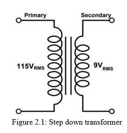
Step Down Transformer
Figure 2.1 shows the circuit schematic of a basic step down transformer. On the left terminals, it can take as input a 115VRMS sinusoid. It will then “step down” the voltage to a 9VRMS sinusoid. It is simple to see that this transformer has a step down voltage ratio of (115:9) or 12.78:1. The ratio for a transformer is set by having the same ratio for the number of turns of wire in the primary coil to the number of turns or wire in the secondary coil. As an example, if one wrapped the first coil with 10,000 turns of wire, the secondary coil would then need to have 782.65 turns of wire to achieve the 12.78:1 ratio. Basic transformer equation is shown below:
𝑉𝑃 = 𝑁𝑃 𝐿𝑃 = √
𝑉𝑆 𝑁𝑆 𝐿𝑆
VP = the primary voltage.
VS = the secondary voltage.
NP = the number of turns in the primary winding.
NS = the number of turns in the secondary winding.
LP = the primary inductance.
LS = the secondary inductance.
Figure 2.1: Step down transformer
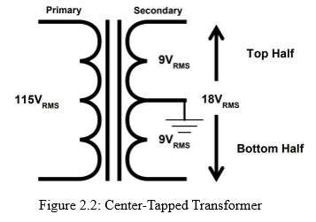
Center-Tapped Transformer
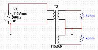
Figure 2.2 shows the circuit schematic of a center tapped step down transformer. The center tapped transformer works almost similar to a normal transformer. The difference lies in just the fact that its secondary winding is divided into two parts, so two individual voltages can be acquired across the two line ends. The internal process is the same, which is when an alternating current is supplied to the primary winding of the transformer it creates a magnetic flux in the core, and when the secondary winding is brought near, an alternating magnetic flux is also induced in the secondary winding as the flux flows through the ferromagnetic iron core and changes its direction with each and every cycle of the alternating current. In this way an alternating current also flows through the two halves of the secondary winding of the transformer and flows to the external circuit.
Figure 2.2: Center-Tapped Transformer
Note: In this example, we are using a 115VRMS to 18VRMS transformer. In a spec sheet for a transformer, if you see the rating: 115VRMS to 18VRMS C.T. (center tapped), this would indicate that the voltage from the top to the bottom of the secondary coil was
18VRMS.
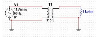
EXPERIMENT 1: Step-Down Transformer
Procedure:
Circuit Construction:
Set up the step-down transformer with the primary side connected to an AC mains supply.
Connect the secondary side of the transformer to a multimeter to measure the output voltage.
Ensure the transformer rating is appropriate for the AC supply voltage and current. o Connect the secondary side of the transformer to the oscilloscope’s input channel (you will be measuring the output voltage waveform).
Ensure the oscilloscope probes are connected with proper grounding.
Measure Input Voltage:
Measure the voltage across the primary winding using a multimeter. This is your input voltage Vp.
Using the oscilloscope, measure and observe the waveform of the AC input voltage at the primary coil. The waveform should be a sinusoidal AC signal.
Record the peak-to-peak voltage, which is your input voltage Vp.
Measure Output Voltage:
Measure the voltage across the secondary winding of the transformer. This is your output voltage Vs.
Measure the secondary voltage waveform by connecting the oscilloscope probe to the secondary coil of the transformer.
The output waveform should also be sinusoidal, but with a lower peak-to-peak voltage compared to the primary side, depending on the turns ratio.
Record the peak-to-peak output voltage Vs and compare the ratio 𝑉𝑠 with the theoretical
𝑉𝑝 turns ratio 𝑁𝑠.
𝑁𝑝
Calculate the Voltage Ratio: 𝑉𝑠 o Based on the input and output voltage readings, calculate the voltage ratio .
𝑉𝑝 o Verify that the ratio is consistent with the number of turns on the primary and secondary coils.
Load Testing (Optional):
Connect a load resistor to the secondary winding as shown below to simulate real-world conditions. Measure the output voltage again under load.
Observe if the voltage drops when the transformer is under load (this will depend on the transformer’s rating and the load resistance).
EXPERIMENT 2: Center-Tap Transformer
Procedure:
Circuit Construction:
Set up the center-tapped transformer with the primary side connected to the AC mains supply.
The secondary side of the transformer has three terminals: one center tap and two end terminals (each a 𝑉𝑠 from the center tap).
Use a multimeter to measure the voltage between each end of the secondary coil and the center tap, and between the two end terminals.
Connect the oscilloscope probe to the center tap and one end of the secondary winding to measure the output voltage across one half of the secondary winding.
Connect a second oscilloscope probe to the other half of the secondary winding (relative to the center tap) to observe the other half of the waveform.
Measure Secondary Voltages:
Measure the voltage between the center tap and one of the end terminals. This should give you 𝑉𝑠.
Measure the voltage between the center tap and the other end terminal. This should also give you 𝑉𝑠.
Measure the voltage between the two end terminals. The voltage between these two points should be Vs, which is twice the voltage measured between the center tap and one end terminal.
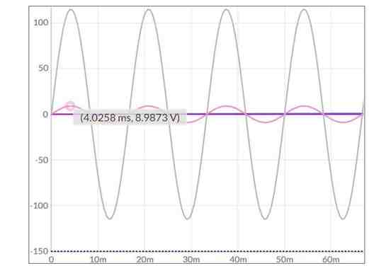
Then, measure the voltage between the center tap and one of the end terminals using the oscilloscope. The waveform should be a sinusoidal signal with a peak-to-peak voltage of 𝑉𝑠.
Next, measure the voltage between the center tap and the other end terminal. The waveform should be similar, with the same peak-to-peak voltage of 𝑉𝑠.
2 o You should see that these two waveforms are 180° out of phase with each other. o Now, measure the voltage across the two end terminals (across the full secondary winding) using the oscilloscope.
This should show a sinusoidal waveform with a peak-to-peak voltage of Vs, which is the total secondary voltage.
Polarities and Phase Relationship: o Verify that the voltages between the center tap and each end terminal are of opposite polarity relative to the center tap.
Verify that the voltages measured between the center tap and each end terminal are of opposite polarity relative to the center tap.
The waveforms should show that they are inverted, meaning they are 180° out of phase.
Load Testing (Optional):
Connect a load resistor to the two end terminals (across the full secondary winding) as shown below. Measure the output voltage and check the current under load.
Connect a load resistor between one end terminal and the center tap to see if you get a voltage of 𝑉𝑠 across the load.
Observe the waveform again under load, noting any changes in the waveform shape, amplitude, or phase.
Using the Oscilloscope to Measure Waveforms:
Voltage Measurement:
Set the oscilloscope to AC coupling mode to eliminate any DC offsets and ensure only the AC waveform is displayed.
Use the oscilloscope’s vertical scale to adjust the amplitude so the full waveform is visible.
Measure the peak-to-peak voltage (or RMS voltage) of the waveforms using the oscilloscope’s voltage measurement function.
Time Measurement (Frequency and Phase): o Set the horizontal scale of the oscilloscope to an appropriate time base, such that one or two full cycles of the waveform are visible.
Measure the frequency of the waveform by looking at the period of the sinusoidal wave on the oscilloscope.
Use the oscilloscope’s cursor or phase measurement function to measure the phase difference between two waveforms, such as between the center tap and end terminal voltages in the center-tap transformer.
Expected Results:
Step-Down Transformer:
Voltage Transformation: o You will observe that the output voltage is lower than the input voltage in the step-down transformer. The voltage ratio should approximately match the ratio of the number of turns on the primary and secondary coils.
For example, if the primary has 100 turns and the secondary has 10 turns, the output voltage should be approximately 1/10th of the input voltage.
The primary voltage waveform will be a sinusoidal signal at the input frequency (g., 50 Hz or 60 Hz depending on the AC mains supply).
Frequency:
The frequency of the output waveform should be the same as the input frequency.
Load Behavior:
Under load, you may observe a slight voltage drop, depending on the load resistance and the current drawn by the load.
Center-Tap Transformer:
Voltage Division:
o The center-tapped transformer will provide two equal voltages of opposite polarity across the secondary winding. 𝑉𝑠 o The voltages between the center tap and the two end terminals will each be .
o The voltage across the two end terminals will be equal to Vs.
Polarity and Phase Difference: o The voltages from the center tap to each end terminal will be of opposite polarity. o The waveforms from the center tap to the two end terminals will be 180° out of phase, meaning that when one voltage is positive, the other is negative.
Load Testing:
When a load is connected between the two end terminals, the output voltage should be Vs.
If the load is connected between one end terminal and the center tap, the output voltage should be 𝑉𝑠 .
Safety Considerations:
Ensure that you are using transformers with appropriate voltage ratings and power ratings for your AC supply voltage.
If working with AC mains, ensure you follow all necessary safety precautions, such as using insulated wires and avoiding contact with exposed terminals.
Always use a multimeter with proper voltage range and verify connections before applying power to the circuit.
Conclusion:
In this experiment, you will have observed how transformers change the voltage levels and how a center-tapped transformer provides dual-output voltages with opposite polarities. By using an oscilloscope to measure the voltage waveforms, you can visually see how the step-down and center-tapped transformers affect AC signals. Additionally, you can verify the theoretical predictions for voltage ratios, waveform shapes, and phase relationships.
Result:
From the waveforms, measure the following parameters for the primary and secondary windings.
VP
V P-P
Vrms
Report
You should capture results based on each condition of your experiments and present them in your report. You may use your phone’s camera to capture your experimental results. You must also include the image of your circuit that you have constructed on your breadboard. Your report should contain a short introduction, procedure, and results you obtain at every stages of the experimental works, discussion and conclusion.
Rubric for Assessing Lab Report
1
Needs improvement
2 Satisfactory
3
Good
4 Excellent
Weightage
Total Score
Introduction/ Pre-Lab
Very little background information provided or information is incorrect
Some introductory information, but still missing some major points
Introduction is nearly complete, missing some minor points
Introduction complete and well-written; provides all necessary background principles for the experiment
2.5
10
Example: 4*2.5=10
marks or
3*2.5=7.5 marks
Experimental procedure/ Methodology
Most of the steps are missing
Missing some of the relevant information about the methods used
The procedures are not in the proper sequences
No circuit diagrams
Some of the steps are missing
Missing some of the relevant information about the methods used
The procedures are not in the proper sequences
Circuit is designed completely but no proper specifications
Lists all steps in a detailed
Missing some of the relevant information about the methods used. The procedures are clearly and systematically stated in correct sequence.
Circuit is designed completely with missing some of the specification.
Lists all steps in a detailed
Contains all of the relevant information about the methods used
The procedures are
clearly and systematically stated in correct sequences Circuit is designed completely as per specifications
4.0
16
Results:
Simulated
results, figures, graphs, tables, etc.
Simulated results, graphs, tables contain errors or are poorly presented, have missing titles, captions or numbers, units missing or incorrect, etc
Most simulated results, graphs, tables are correctly presented, some still missing some important or required features
All simulated results, graphs, tables are correctly presented, but some have minor problems or could still be improved
All simulated results, graphs, tables are correctly presented, are numbered and contain titles/captions
8.0
32
Discussion
Very incomplete or incorrect interpretation of trends and comparison of data indicating a lack of understanding of results
Some of the results have been correctly interpreted and discussed; partial but incomplete
understanding of
results is still evident
Almost all of the results have been correctly interpreted and discussed, only minor
improvements are needed
All important trends and data comparisons have been interpreted correctly and discussed, good understanding of results is conveyed
7.5
30
Conclusion
No attempt was made to conclude. Lab questions were not answered.
Conclusion is derived from the simulated and analysed data but is not answering the lab questions or objectives.
Conclusion is good and derived from the simulated and analysed data and not from other sources and directly answer the lab questions or objectives.
Conclusion is excellent and derived from the simulated and analysed data and not from other sources. Conclusion clearly answers the lab questions or objectives.
3.0
12
TOTAL Score
(𝑻𝒐𝒕𝒂𝒍𝟏𝟎𝟎 𝑺𝒄𝒐𝒓𝒆 × 𝟏𝟓50%% )
Remarks: Applicable for Lab 1-Lab
END OF ASSIGNMENT 2
100% Original TEE208 Assignments by Electrical Engineering Experts
Wawasan Open University students often struggle with TEE208 Circuit Theory II assignments because passive filters, transfer functions, frequency response analysis, and transformer experiments require strong theoretical understanding and accurate lab reporting. Capturing experimental results, plotting graphs, analysing phase shifts, and meeting strict plagiarism rules can be time-consuming. There is no need to worry, as Malaysia Assignment Help provides expert Circuit Theory Assignment Help aligned with engineering standards. For trust, students can explore our WOU assignments with expert help. Order your TEE208 Assignment 2 today through our assignment help and receive 100% original, well-documented lab reports written only for you.
Answer
UP TO
15
%DISCOUNT
Instant Paper Writing Services by Native Malaysia Writers