

Convincing Features

Assignment Type
Subject
Uploaded by Malaysia Assignment Help
Date
FACULTY OF ELECTRICAL ENGINEERING UNIVERSITI TEKNOLOGI MALAYSIA 2025/2026-1
Cranes are machines that are used for transporting payloads or hazardous materials from one place to another place. These actions commonly take place in industries such as factories, construction, marine industries and harbour loci. Numerous types of cranes are widely used in many industrial sectors, such as an overhead or bridge crane, a gantry crane, a boom crane and a rotary (tower) crane. In industries, a fast and accurate positioning of trolley and payload is desirable as this translates into a higher production rate. However, a fast response results in an excessive payload oscillation which is undesirable as it may be harmful to human and nearby equipment. Figure 1 shows an actual gantry crane used in industry.
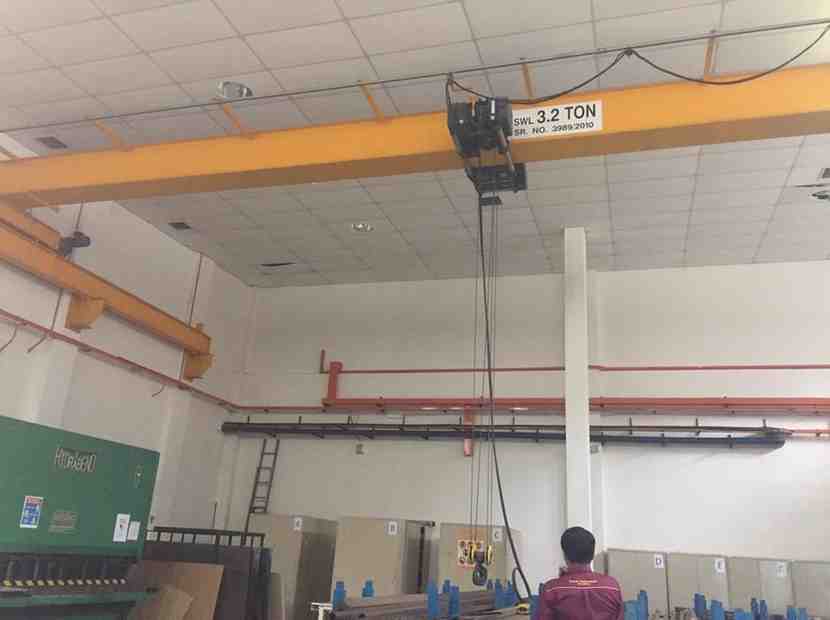
Figure 1: A gantry crane system
This assignment is designed to enhance student understanding in analysis and design of control systems. It is also intended to familiarise the students with computer aided design techniques and to the valuable nature of software package in control systems engineering. Simulations should be carried out using MATLAB/Simulink. A great deal of flexibility and freedom is given to the students to think through various issues and solve the problems.
For the purpose of modelling, simulation, analysis and controller design, the crane system can be represented by a schematic diagram shown in Figure 2. All the symbols are listed in Table 1.
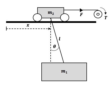
Figure 2: The schematic diagram
Table 1: List of symbols
| 𝑚! | Payload mass | 𝑔 | Gravity | 𝑟 | Gear ratio |
| 𝑚“ | Trolley mass | 𝐵 | Damping coefficient | 𝐿 | Inductance |
| 𝑙 | Cable length | 𝑉 | Input voltage | 𝑖 | Armature current |
| 𝑥 | Trolley displacement | 𝑅 | Resistance | 𝑇# | Load torque |
| 𝜃 | Payload swing angle | 𝐾$ | Motor torque constant | 𝑇% | Motor torque |
| 𝑇 | Torque | 𝐾& | Electric constant | 𝜃% | Rotor angle |
| 𝐹 | Driving force | 𝑝 | Radius of pulley | 𝐽% | Motor inertia |
This is a similar task given in the SKEE3133 course last semester (2020/2021-1). Please revisit your derivations and analyses of the dynamic model. For those who are new, you are required to derive the model according to the following description.
The purpose of modelling is to obtain a mathematical equation representing a dynamic model of the crane. It is important to obtain an accurate model, to ensure correct simulation results and to have a reliable real-time implementation. One of the most widely used techniques for modelling of mechanical systems is using a Lagrange equation based on the kinetic and potential energies of the system.
Considering Figure 2 and by using the Lagrange equation, the differential equation of the trolley and payload (without a DC motor) can be obtained as:
(𝑚! + 𝑚“)𝑥̈ + 𝑚!𝑙𝜃̈ cos 𝜃 − 𝑚!𝑙𝜃̇” sin 𝜃 + 𝐵𝑥̇ = 𝐹 (1)
𝑚!𝑙“𝜃̈ + 𝑚!𝑙𝑥̈ cos 𝜃 + 𝑚!𝑔 𝑙 sin 𝜃 = 0 (2)
The trolley is actuated by a DC motor and a pulley. The following formulations show the relationships between the DC motor parameters, the pulley, the generated torque and the voltage input.
𝑉 = 𝑅𝑖 + 𝐿 ’$’( + 𝐾&𝜃̇% (3)
𝑇% = 𝐾$𝑖 (4)
When L is small and neglected, Equation (3) becomes:
𝑉 = 𝑅𝑖 + 𝐾&𝜃̇% (5)
By applying the Newton’s second law of motion to the motor shaft, an equation is obtained as:
𝐽%𝜃̈% = 𝑇% − )*! (6)
Considering a very small 𝐽%, Equation (6) can be written as:
𝑇% = )*! (7)
Equations related the horizontal motions are:
𝑇# = 𝐹𝑝 (8)
𝜃% = * 𝑥 (9)
a) By combining the motor equations (Equations (4), (5), (7), (8) and (9)) with the crane equation in Equation (1), show that the differential equation of Equation (1) can be written as
𝐴!𝑥̈ + 𝐵!𝑥̇ + 𝐶!@𝜃̈ cos 𝜃 − 𝜃̇” sin 𝜃A = 𝑉 (10)
where
𝐴! = (𝑚! + 𝑚”) -,+”* (11)
𝐵! = .,+–“* + + (12)
𝐶! = 𝑚!𝑙 ,+ (13)
b) Equations (2) and (10) are the nonlinear differential equations representing the dynamic model of the crane system with a DC motor.
For simplicity in control design, nonlinear differential equations can be linearized, to obtain a linear model, by assuming 𝜃 small. This yields cos 𝜃 ≈ 1 and sin 𝜃 ≈ 𝜃.
By using the assumptions, show that Equations (2) and (10) can be linearized to yield linear differential equations as:
𝐴!𝑥̈ + 𝐵!𝑥̇ + 𝐶!𝜃̈ = 𝑉 (14)
𝑙𝜃̈ + 𝑥̈ + 𝑔𝜃 = 0 (15)
c) Subsequently, by using the linear differential equations find the following transfer functions of the system:
i) The trolley displacement, 𝑥(𝑡) with respect to the voltage input.
ii) The payload angle, 𝜃(𝑡) with respect to the voltage input.
Task 2: Analysis of an Open-Loop System
It is important to analyse the dynamic characteristics of the gantry crane system, for design of an efficient controller. Table 2 shows the parameters of the gantry crane.
Table 2: Gantry crane parameters
| Parameters | Value (unit) | Parameters | Value (unit) |
| Payload mass, m1 | 1.0 kg | Resistance | 2.6 W |
| Payload mass, m2 | 5.0 kg | Torque constant | 0.007 Nm/A |
| Cable length, l | 0.75 m | Electric constant | 0.007 Vs/rad |
| Gravitational acceleration | 9.81 m/s2 | Radius of pulley | 0.02 m |
| Damping coefficient | 0.01 Ns/m | Gear ratio | 0.15 |
a) Write a MATLAB file (m-file) to:
i) Represent the transfer functions of the system in MATLAB with the system parameters.
ii) Find the system poles and zeros, and plot the pole-zero map. Discuss its stability.
iii) Change the values of the cable length, 𝑙 and the payload mass, 𝑚! and observe the effects on the poles and zeros, and stability.
b) Develop a Simulink model to investigate the dynamic characteristic of the crane system. Two responses related to the trolley and payload should be obtained and analysed. Use the system parameters given in Table 2. For this task, the input is a bang-bang input voltage with an amplitude of ± 5 V and the period of 2 secs, as shown in Figure 3.
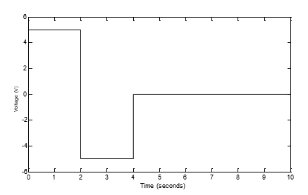
Figure 3: The input voltage
i) Obtain the time responses of the trolley displacement and the payload swing angle.
ii) Convince yourself that the responses are practical and correct. This is one of the approaches to validate the correctness of the dynamic model.
iii) Discuss the performance of the open-loop system.
iv) Is the payload sway response acceptable?
v) You can also investigate the effects of using different cable length, 𝑙 and the payload mass, 𝑚! on the system responses.
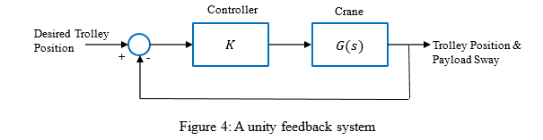
For the purpose of controlling the crane, the system is configured to be in a unity closed-loop feedback system as shown in Figure 4 where K is a feed-forward gain. Throughout this assignment the trolley is required to move to a distance of 2 meters to place a payload.
a) Plot a root locus of the system. Observe the system stability with changing K.
b) By using an appropriate value of K (for example, 𝐾 = 50), obtain Bode plot of the system. Determine the gain margin and phase margin of the system, and discuss its stability.
c) Convince yourself that both results in time and frequency domains are identical in terms of their stability property.
For an efficient production line, the trolley of the gantry crane is required to operate with the following time response specifications:
The closed-loop system is enhanced by using a controller connected in series with the gantry crane as shown in Figure 5.
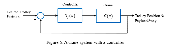
a) Design a PD controller using a root locus technique to achieve the required specifications. As the root locus is used for design, and the closed-loop system responses are required, you may need to use both the MATLAB Workspace and Simulink in the controller design process.
i) Calculated and find an appropriate PD controller.
ii) Investigate whether that the desired closed-loop poles can be obtained by using the proposed PD controller. This can be shown by analysing the root locus of the complete system.
iii) The Simulink block diagram in Task 2 can be enhanced to include the controller. In this case, the PID block in Simulink can be utilised. Using the calculated PD gains, observe the time response of the trolley position response. A step signal of 2 meters should be used as the input. iv) The response of the payload sway should also be observed. Is it affected by the performance of trolley response?
b) In theory, a PID controller can used to obtain a satisfactory time response together with a zero steady-state error. Design a PID controller to further enhance the performance of the gantry crane system to achieve a zero steady-state error. As similar time response specifications for the trolley position are required, the previously designed PD controller can be augmented with a PI controller.
i) Identify an appropriate PI controller. Then, use a root locus to design a PID controller, and find the three PID gains.
ii) Observe the trolley and payload sway responses with the PID controller.
iii) For this crane system, do you think the PID controller is a right controller to improve the system performance? State your reasons.
Besides the root locus technique, there are several other approaches for tuning of the PID controller gains. These include classical Ziegler-Nichols and Cohen-Coon techniques. Moreover, with the advanced of computing technology, optimal PID gains can also be obtained by using an optimisation algorithm. In Simulink, a PID tuner can be explored to find optimal and appropriate gains to achieve the desired specifications.
In this task, you are required to explore the application of the PID tuner in Simulink. The following steps can help to access and use the PID tuner:
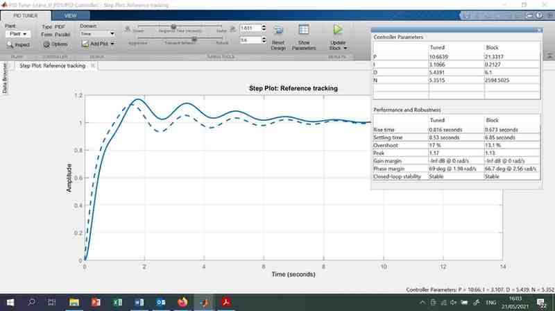 Figure 6: PID Tuner in Simulink
a) Tune the PID controller to achieve the best specifications in terms of overshoot, settling time and steady-state error, together with a satisfactory payload sway response. Note that a very fast trolley movement might result in an excessive payload oscillation which is undesirable. Use the tuned PID gains in the Simulink model to verify the trolley and payload sway responses.
b) You can also investigate and design a PD controller.
c) Discuss your controller designs and the results.
One of the control design approaches in frequency domain is by using the Bode plot. In this case, the Bode plot of the original unity feedback system obtained in Task 3 can be considered as an uncompensated system.
a) By using a gain adjustment method, determine a proportional controller so that the trolley position response moves to the desired distance with an overshoot of 10%.
i) Find the appropriate gain, K.
ii) Convince that the required Bode plot specification is achieved.
iii) Use Simulink to investigate the time responses of the trolley and payload sway. Observe and discuss the simulation results.
b) To further improve the efficiency of the production line, the trolley position response is required to move with the following specifications:
i) Design a lead compensator to achieve the desired specifications. A correction factor might be required.
ii) Obtain the Bode plot of the compensated system, and investigate whether the desired Bode plot specifications are achieved. These involve investigating the phase margin and bandwidth.
iii) Use Simulink to obtain the compensated system responses, and discuss the results.
iv) Give your comments whether the lead compensator is a suitable controller for this system.
This assignment contributes 20% of the total mark. Each group is required to analyse and design controllers of the gantry crane system as described in Tasks 1-6. All group members must actively contribute in this assignment.
As most of the desired specifications are given within a certain range, all the groups should try to design a controller to achieve the best results.
Assessment will be done according to the following:
The SKEE3143 Control System Design assignment at UTM is highly technical and often challenging due to complex modelling, MATLAB/Simulink simulations, and controller design accuracy. Many students struggle with gantry crane dynamics, PID tuning, and meeting strict time-response specifications. At Malaysia Assignment Help, we deliver 100% human-written, AI-free assignments answers aligned with UTM rubrics. Get expert guidance from Control System Assignment Help specialists for modelling, analysis, and simulation tasks. Start confidently with trusted support from Assignment Helper.